
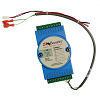
Can a dry-contact smart relay be connected directly to my garage door opener’s wall-button terminals?
Yes, but only when the opener uses a true momentary dry-contact command input and the smart relay provides an isolated, voltage-free, normally open output. Many newer openers use digital or coded wall controls instead. Those systems may require a manufacturer-approved adapter, wireless interface, or compatible remote rather than direct connection across the wall-console terminals.
What a Dry-Contact Relay Actually Does
A dry-contact relay acts like a switch. When activated, it briefly joins two relay terminals without supplying voltage of its own. On a conventional residential opener, that momentary closure can duplicate the action of a basic wall push button.
For a direct connection to be appropriate, the opener manual must identify the terminals as a push-button, single-button, step-by-step, or momentary contact input. The smart relay output should normally be connected in parallel with the existing wall button so either device can command the opener. The original control should not be removed unless the opener and smart-controller instructions specifically call for it.
Technical Field Note: “Dry Contact” Describes the Relay Output
The phrase does not mean every low-voltage terminal on the opener accepts a contact closure. A relay can be electrically isolated and still be connected to the wrong circuit. Compatibility depends on the opener input logic as well as the relay output.
When Direct Wiring Usually Works
Direct wiring is commonly possible when the existing wall control is a simple, non-powered push button with one command pair. Pressing the button temporarily closes the same two conductors that return to the opener’s control terminals. In that design, a normally open smart relay can often be placed across the identified command pair.
Before connecting it, verify all of the following:
- The opener documentation identifies a momentary contact command input.
- The relay output is isolated and voltage-free.
- The relay can be configured as normally open and momentary, not maintained.
- The pulse time matches the controller instructions and does not hold the input closed.
- The relay is connected to the command and common terminals, not accessory power.
- The existing wall button remains functional after the parallel connection.
A maintained relay output can hold the command circuit closed. Depending on the opener, that may cause ignored commands, lockout behavior, repeated cycling, or an abnormal control state. Use the momentary or pulse mode specified for the smart controller.
When the Wall-Button Terminals Are Digital or Coded
Many multifunction wall consoles communicate digitally over two low-voltage wires. The same conductors may carry door commands, light control, vacation lock, motion sensing, timer functions, programming, and diagnostic data. Shorting those wires does not necessarily produce an open-close command.
Two wires therefore do not prove that the circuit is dry contact. If the wall console has several function buttons, a display, motion sensor, learn controls, or status indicators, treat the circuit as potentially coded until the manual confirms otherwise.
A digital system may require one of three alternatives:
- A manufacturer-approved dry-contact or protocol adapter
- A smart controller that pairs wirelessly through the opener’s receiver
- A compatible remote-control interface activated by the smart module
Technical Field Note: Connector Shape and Terminal Color Are Not Logic Diagrams
Different opener generations may reuse similar terminal blocks while changing the electrical function. Match the exact opener model, logic-board number, wall-console part number, and production generation instead of assuming that red, white, black, or numbered terminals always perform the same job.
Never Use Safety-Sensor or Accessory-Power Terminals
Photo-eye terminals are part of the opener’s monitored safety circuit, not an alternate command input. Accessory-power terminals may supply voltage for sensors or controls. Connecting a dry-contact relay across either circuit can create faults, damage hardware, or interfere with required safety operation.
Do not bypass photo eyes, force logic, monitored inputs, warning devices, or other entrapment-protection functions to make smartphone control work. The door should already close normally from the approved controls, reverse when the photo-eye beam is interrupted, and move freely without excessive drag before a smart command device is added.
Single-Button Inputs Versus Open-Close-Stop Controls
Most residential openers use one momentary command that cycles through open, stop, and close according to the control board’s current state. Some commercial or specialty operators use separate open, close, and stop inputs. A one-channel smart relay should not be assumed to duplicate a three-button control station.
For separate-input systems, verify the required normally open or normally closed logic for each function, the common terminal arrangement, and whether constant-pressure closing is required. A residential smart-garage relay may be unsuitable even if the operator has terminals labeled OPEN and CLOSE.
How to Verify the Terminals Before Connection
- Record the opener brand, full model number, serial number, and manufacture date.
- Photograph the logic-board label, wall-control terminals, and existing wire positions.
- Record the wall-console part number and its available functions.
- Check the opener wiring diagram for a momentary contact input.
- Confirm the smart relay’s output type, contact rating, pulse mode, and channel count.
- Determine whether an adapter or paired remote is listed for that opener generation.
- Verify that the smart system includes reliable door-position monitoring.
A continuity test across a disconnected basic push button can help identify whether the button itself closes a contact. It does not prove that every terminal at the motor head is safe to short. When terminal functions are unclear, use the opener manual and the smart-controller compatibility chart rather than experimenting on the board.
Technical Field Note: Replacement Boards Can Change the Answer
An opener may retain its original housing and model label after a logic-board replacement. The installed board may use a different wall-control protocol or receiver generation. When the board, learn button, and wall console do not match the original parts diagram, verify compatibility against the installed electronics.
Technician’s Corner
South Florida humidity and salt-air exposure can corrode low-voltage conductors and terminal screws. A relay may test correctly at the module but fail intermittently at the opener because of oxidized splices or moisture-damaged wiring. Lightning and utility surges can also damage one control input while leaving the motor and another command source operational.
Before adding the relay, test the wall button, remotes, safety sensors, travel, reversal, and manual door balance. After connection, confirm that local controls still work, the relay releases after each pulse, the app reports the correct door position, and a network interruption does not leave the command output latched.
Related Technical Categories
- Smart Garage Controllers
- Garage Door Wall Consoles and Control Panels
- Garage Door Opener Logic Boards
- Garage Door Safety Sensors
- Garage Door Opener Receivers
- Garage Door Opener Remotes
Before selecting a dry-contact smart relay, verify the opener model number, board generation, wall-console part number, terminal function, relay mode, voltage isolation, connector type, safety-sensor configuration, and required adapter. Direct connection is appropriate only when both the opener input and the relay output are designed for the same momentary contact logic.
