
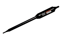
Why do GTO Pro replacement arms have different cable lengths, and which cable length do I need?
GTO Pro replacement arms use different cable lengths because the primary arm normally mounts beside the control box, while the secondary arm on a dual gate must reach that same box from the opposite leaf. Choose the cable supplied for the exact arm model and system position—not simply the longest cable available or the measured driveway width.
Cable Length Identifies the Arm’s Intended Position
On a single swing gate, the actuator and control box are normally installed on the same gate post. The primary, master, or first-operator arm therefore uses a short factory cable. In a dual system, the secondary, slave, or second-operator arm is installed on the opposite leaf, so its cable must cross the entrance through protected conduit and return to the primary control enclosure.
The cable is part of the actuator assembly’s model identity. It carries motor power and the conductors used by the operator’s travel-feedback or rev-counter system. It is not equivalent to a two-wire push-button cable or a simple dry-contact accessory lead. Cable resistance, conductor arrangement, polarity, connector style, strain relief, and moisture protection all affect operation.
Common GTO Pro XLS Cable-Length References
| Operator Family | Arm Role | Common Cable Reference | Selection Note |
|---|---|---|---|
| SW2000XLS | Primary or single-gate arm | 6 ft | Used on the control-box side |
| SW2002XLS | Secondary arm | 32 ft | Used for the opposite leaf in the matched 2000XLS dual system |
| SW3000XLS | Primary or single-gate arm | 6 ft | Used on the control-box side |
| SW3200XLS | Secondary arm | 40 ft | Long cable routes from the far leaf to the primary enclosure |
| SW4000XLS | Primary or single-gate arm | 6 ft | Heavy-duty primary arm for the control-box side |
| SW4200XLS | Secondary arm | Verify current package label | Listings may differ between 40 ft and 50 ft references; confirm the actual part and cable before selection |
Earlier XL generations also use short primary cables and longer secondary cables, but their arm part numbers and lengths must be checked separately. Do not use an XLS cable-length chart to identify an XL arm, and do not assume that a 3000-series or 4000-series actuator fits another family because the cable length matches.
Choose by Model and Role Before Measuring the Route
First identify the complete actuator model, including XL or XLS and the primary or secondary designation. Then trace the existing cable to the control board. A short cable connected to the master, primary, or first-operator terminals normally identifies the primary arm. A cable routed across the driveway and connected to the slave, secondary, or second-operator terminals normally identifies the secondary arm.
Next, measure the proposed route through the actual conduit path, including vertical rises, sweeps, entry into the enclosure, service loops, and routing around posts. Driveway opening width alone is not the required cable length. The route must be long enough without placing tension on the actuator cable or connector.
If the factory cable listed for the correct arm appears too short, inspect the layout before substituting another actuator. The control box may be mounted on the wrong side, the conduit may take an unnecessarily long route, or the system may use a different secondary-arm generation. A longer cable does not make an otherwise incorrect arm compatible.
Do Not Convert a Primary Arm With Ordinary Extension Wire
Adding field wire to a 6-foot primary-arm cable is not the same as using the model-specific secondary assembly. A splice can introduce motor-voltage drop, intermittent feedback signals, corrosion, water intrusion, and conductor-identification errors. These faults may cause slow movement, uneven dual-gate travel, limit-learning problems, false obstruction response, or an arm that works only in dry weather.
Likewise, do not shorten a long secondary harness or replace its connector unless the current manufacturer instructions specifically permit the modification. Factory cable construction, seals, strain relief, and connector pinout are part of the complete service assembly.
Technician’s Corner
Underground Distance Is Not the Only Distance
A 16-foot entrance may require considerably more than 16 feet of cable after accounting for conduit rises, sweeps, post height, enclosure entry, and service slack. Measure the complete protected path before routing the cable.
Water-Filled Conduit Can Make the Cable Look Too Small
South Florida rain, irrigation, and condensation can enter damaged conduit and corrode splices or conductor ends. A cable may show continuity with a meter but develop excessive voltage drop when the motor operates. Test conductor resistance and operating voltage at the far arm when diagnosing a suspected cable fault.
Do Not Share Conduit With AC Power
Keep actuator and receiver wiring separated from line-voltage conductors as directed by the operator manual. Shared conduit increases electrical-noise and safety concerns and can complicate troubleshooting of feedback signals.
Extra Cable Does Not Change Arm Compatibility
A 40-foot or 50-foot secondary cable does not turn a 3000-series arm into a 4000-series arm. Stroke, motor, gearing, operating speed, feedback components, mounts, and control-board application still need to match.
Before You Choose a Replacement Arm
- Record the full operator and actuator model, including XL or XLS.
- Identify primary, master, or first-operator versus secondary, slave, or second-operator use.
- Confirm the original arm part number and factory cable length.
- Photograph the connector, conductor colors, board terminals, cable entry, and any existing splice.
- Measure the complete conduit route rather than only the driveway opening.
- Inspect the conduit for water, crushed sections, sharp bends, and shared AC wiring.
- Verify actuator stroke, retracted length, feedback system, bracket geometry, and board generation.
- Test the existing cable and secondary board output before condemning the arm.
Related Technical Categories
- Swing Gate Openers
- Gate Opener Replacement Parts
- Gate Opener Circuit Boards
- GTO Pro Replacement Actuator Arms
- Gate Operator Cable, Conduit, Batteries, and Safety Devices
Select the replacement arm by exact model, operator generation, primary or secondary role, and factory cable configuration. Before choosing hardware, verify the part number, voltage, connector type, conductor arrangement, cable length, control-board revision, actuator feedback system, mounting geometry, and protected routing distance.
