
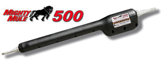
Which Mighty Mule replacement arm is compatible with my existing control board?
The correct Mighty Mule replacement arm must match the operator model, control-board family, and primary or secondary gate position. A shared board number does not make every actuator interchangeable. Verify the complete opener model, arm label, cable length, harness connector, gate capacity, and board part number before selecting an RP271ARM, RP272ARM, RP371ARM, RP372ARM, RP571ARM, or RP572ARM.
Start With the Board Part Number and Operator Model
Open the control enclosure only after disconnecting the battery, transformer, and solar input. Record the complete part number printed on the logic board and the model number shown on the operator or actuator label. Board color, enclosure shape, receiver frequency, and connector appearance are secondary clues; none should be used as the sole compatibility test.
Current Mighty Mule systems fall into several distinct electrical and mechanical families. The MM271 uses an arm assembly with an integrated control board. The MM272 uses a separate dual-gate board and dedicated primary and secondary actuators. The MM371W, MM372W, MM571W, and MM572W share the RP1007 replacement logic board, but their actuator capacity and cable configurations remain model-specific.
Current Mighty Mule Arm and Board Compatibility
| Existing system | Control-board family | Primary or single-gate arm | Secondary arm |
|---|---|---|---|
| MM271 | Board integrated with operator arm | RP271ARM | Not applicable |
| MM272 | RP1003 | RP272ARM1 | RP272ARM2 |
| MM371W | RP1007 | RP371ARM | Not applicable |
| MM372W | RP1007 | RP371ARM | RP372ARM |
| MM571W | RP1007 | RP571ARM | Not applicable |
| MM572W | RP1007 | RP571ARM | RP572ARM |
Why the Shared RP1007 Board Does Not Make the Arms Universal
The RP1007 board is approved for the MM371W, MM372W, MM571W, and MM572W families. That means one board platform can control either the medium-duty 371/372 actuators or the heavy-duty 571/572 actuators. It does not mean an RP371ARM should replace an RP571ARM or that a secondary RP372ARM should replace an RP572ARM.
The arm must still match the gate’s rated model family, physical stroke and mounting geometry, motor and feedback arrangement, cable length, and primary or secondary connection. Replacing a heavy-duty arm with a medium-duty arm can leave the system mechanically undersized even if the connector fits and the board powers the motor.
Primary and Secondary Arms Are Different Parts
On dual gates, the primary arm is installed near the control box and uses a short cable. The current RP371ARM and RP571ARM each include a 6-foot cable. The secondary actuator must reach the second gate leaf and therefore includes a substantially longer cable: 40 feet for the RP372ARM and 44 feet for the RP572ARM.
Do not identify the arm by housing appearance alone. Confirm which control-board terminals the existing cable uses, whether it is the first or second operator, and the exact label on the actuator. A short primary lead should not be extended casually to imitate a factory secondary arm; resistance, splices, moisture intrusion, and conductor routing can affect operation.
Technician’s Corner
Technical Field Note: A Loaded Control Box Can Hide the Original Model
The RP1004 loaded control box is associated with the MM371W, MM372W, MM571W, and MM572W families. If the original enclosure was replaced, the control-box label may identify the shared service assembly rather than the exact gate model. Use the actuator label, gate capacity, number of leaves, and cable configuration to separate the 371/372 and 571/572 systems.
Technical Field Note: Similar Plugs Do Not Prove Electrical Compatibility
Two arms may use connectors that look alike while differing in motor load, feedback components, cable pinout, or approved board family. Never move wires within a plug or adapt a harness without a verified wiring diagram. A wrong connection can damage the logic board, actuator, rev-counter circuit, or limit system.
Technical Field Note: Lightning Damage May Affect More Than the Board
South Florida surge and lightning exposure can damage the board, actuator feedback circuit, transformer, battery charging section, accessories, and underground secondary cable during the same event. Replacing the arm before checking board output, cable continuity, and power condition can misdiagnose the failure.
Technical Field Note: Legacy R4211 Systems Need Separate Verification
The R4211 replacement board is approved for FM500/FM502, MM560/MM562, and MM600/MM660 systems and includes the R5040 harness. Do not assume a current RP371ARM or RP571ARM is a direct substitute because the board is newer or the connector appears compatible. Match the original legacy operator model, approved arm assembly, rev-counter components, and parts diagram.
Before You Match a Mighty Mule Replacement Arm
- Record the complete opener model and serial number.
- Photograph the board part number, revision, terminals, and harness plugs.
- Record the existing actuator label and primary or secondary position.
- Measure the attached cable and note any underground splices or corrosion.
- Confirm gate length, weight, construction, hinge condition, and free movement.
- Verify the replacement against the correct manual and parts diagram.
Before selecting replacement hardware, verify model number, part number, voltage, receiver frequency, connector type, board generation, actuator position, cable length, and required safety-device compatibility. After replacement, recheck limits, obstruction or stall-force settings, dual-gate sequencing, and all monitored entrapment-protection inputs required by the operator.
Related Technical Categories
Mighty Mule Replacement Arms | Mighty Mule Control Boards | Mighty Mule Loaded Control Boxes | Swing Gate Operator Parts | Gate Opener Batteries | Solar Gate Power | Gate Safety Devices | Automatic Gate Locks
