
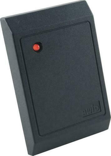
How far away can a proximity reader be installed from the access control panel?
A proximity reader can often be installed several hundred feet from its access panel, but the exact limit depends on whether it uses Wiegand, OSDP, or another interface. Wiegand is commonly limited to about 500 feet, while some OSDP systems support much longer runs. Cable type, voltage drop, current draw, grounding, topology, and manufacturer limits control the final distance.
Start With the Reader Interface
The distance limit is not determined by the credential frequency. A 125 kHz or 13.56 MHz reader may connect to the controller through Wiegand, OSDP over RS-485, or a proprietary interface. The reader-to-controller protocol determines the data-wiring requirements, while the reader’s voltage and current draw determine whether it can be powered reliably at the far end.
Always verify the exact reader and controller manuals. A general protocol may be capable of a long run, but a specific device can have a shorter published limit because of its electronics, supported baud rate, terminal design, cable specification, or power requirements.
Wiegand Runs Are Commonly Limited to About 500 Feet
Many Wiegand reader and controller specifications publish a maximum distance near 500 feet when the recommended shielded cable and conductor size are used. Wiegand normally requires power, ground, Data 0, and Data 1, with additional conductors for LED, beeper, tamper, or hold functions.
The 500-foot figure should not be treated as a universal guarantee. Cable capacitance can distort the Data 0 and Data 1 pulses. Electrical noise from gate motors, variable-frequency equipment, line-voltage conductors, or poor grounding can reduce reliability. Corroded splices, underground cable damage, and an inadequate signal ground can cause changing bit counts or intermittent invalid-card events even when the reader still powers up.
OSDP Can Support Longer Data Runs
OSDP uses bidirectional RS-485 communication. Some systems publish data distances up to approximately 4,000 feet when the correct cable, baud rate, topology, and termination are used. This makes OSDP useful when the controller is located far from a vehicle gate, guard station, or remote pedestrian entrance.
Long OSDP runs require proper RS-485 practices. Use the cable specified by the controller and reader manufacturers, maintain data-pair polarity, assign unique reader addresses, and follow the permitted bus layout. OSDP is commonly wired as a daisy chain rather than a star. Long branches, multiple terminations, missing end-of-line termination, or duplicated addresses can produce intermittent device-offline faults.
Existing Wiegand cable may sometimes be reused for OSDP, but conductor count alone is not enough. Confirm that a suitable twisted pair is present, the insulation and shield are intact, and the cable route is appropriate for RS-485 communication.
Data Distance and Power Distance Are Separate
A reader can have a reliable data path while receiving inadequate operating voltage. Voltage drop depends on supply voltage, reader current, wire gauge, conductor material, connection resistance, and the complete out-and-back conductor length. Multi-technology readers, keypads, illuminated readers, Bluetooth radios, and heaters may draw more current than a basic proximity reader.
Measure voltage at the reader while it is connected and operating. A no-load measurement at the controller does not show the voltage available during card reads, keypad use, LED changes, or radio activity. If the reader voltage falls below its specified input range, it may reset, shorten its read range, flash unexpectedly, or communicate intermittently.
For a very long run, a properly specified local power supply near the reader may reduce voltage-drop problems. The controller and reader manuals must still be followed for signal reference, grounding, backup power, supervision, and surge protection. Do not connect two power sources together unless the equipment documentation specifically permits that arrangement.
Cable Gauge and Current Draw Change the Practical Limit
A larger conductor has less resistance and usually produces less voltage drop than a smaller conductor of the same length. However, increasing only the power-conductor size does not correct excessive data-line capacitance, incorrect RS-485 topology, or electrical interference.
Calculate the expected voltage drop using the replacement reader’s maximum or peak current rather than only its typical current. Include all devices powered through the same conductors, such as a keypad, display, heater, request-to-exit device, or interface module. Verify the controller’s per-port and total accessory-current capacity before increasing the reader load.
Outdoor Gate Locations Add Environmental Risks
Reader cable at a gate often shares an underground route with loop leads, operator control wiring, communication cables, or power circuits. Follow required separation and grounding practices. Protect the reader and controller wiring as specified for outdoor exposure, and use suitable enclosures, junctions, and surge-protection devices.
South Florida lightning, humidity, salt air, flooding, insects, and condensation can turn a theoretically acceptable cable run into an unreliable one. Water intrusion or corrosion may add resistance to the power conductors or leakage between data conductors. Inspect the entire route instead of assuming that distance alone is the problem.
Technician’s Corner
Technical Field Note: If a reader works on a short temporary cable at the panel but fails at the gate, compare voltage under load and inspect the permanent cable before replacing the reader.
Technical Field Note: A stable but incorrect Wiegand card number can indicate reversed Data 0 and Data 1 or format programming. A changing bit count is more consistent with cable, noise, grounding, or pulse-quality problems.
Technical Field Note: OSDP readers can remain powered while appearing offline. Check address, polarity, topology, termination, and controller port mode before assuming the distance is excessive.
Technical Field Note: Long data capability does not eliminate power calculations. A 4,000-foot RS-485 rating does not mean the controller can power every reader over the same 4,000-foot conductors.
Before You Plan the Reader Run
- Identify the reader and controller models, firmware, and interface type.
- Confirm the manufacturer’s maximum distance and required cable.
- Record reader voltage, normal current, peak current, and controller power capacity.
- Calculate voltage drop using the complete circuit length and selected wire gauge.
- Verify Wiegand capacitance limits or OSDP topology, address, and termination.
- Plan grounding, shielding, surge protection, conduit separation, and local power if needed.
- Measure voltage and communication performance at the installed reader under load.
Related Technical Categories
- Proximity Card Readers
- Wiegand and OSDP Readers
- Gate Access Controllers
- Access Control Power Supplies
- Low-Voltage Surge Protection
- Reader Interface Modules
Before selecting reader hardware or cable, verify model number, protocol, voltage, current draw, wire gauge, conductor count, cable capacitance, shielding, connector or terminal type, maximum distance, firmware, controller generation, and outdoor installation conditions. Use the exact reader and controller specifications rather than a general protocol distance alone.
