
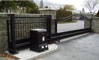
The slide gate stops at a different position every few cycles. Is that a limit switch, magnet, encoder, chain, or control board problem?
If a slide gate stops at a different position every few cycles, suspect an intermittent position signal, slipping drive component, unstable wiring connection, or control-board interpretation problem before assuming one fixed obstruction. Limit switches, magnets, encoders, chain or clutch slip, and board inputs can all affect travel, but the diagnostic LEDs and repeatability pattern should narrow the cause.
Random Stop Positions Point Away From One Fixed Obstruction
The first diagnostic clue is whether the failure position repeats. A bent track, damaged wheel, tight guide roller, or rack alignment problem usually creates resistance near the same physical location. The operator encounters that problem each time the same section of gate travels through the affected area.
A gate that stops three feet from closed on one cycle, eight feet from closed on another, and near mid-travel several cycles later has a different failure pattern. Position feedback, intermittent wiring, drive slip, power under load, or changing control inputs move higher on the suspect list.
Do not rely on memory when comparing stop positions. Mark the gate location with removable tape or record a short video of several failed cycles. Also note whether the operator stops, reverses, resets, or reports an error. These are different controller responses.
Technical Field Note: Random is a diagnostic pattern
A control board does not know the gate is physically ten feet from the post unless the operator's position system tells it. Depending on the design, that information can come from limit switches, magnets, an encoder, RPM or Hall-effect feedback, or electronically learned travel. An unstable position signal can make the physical stop point change from cycle to cycle.
Check Limit Switches, Cams, and Limit Nuts
Some slide operators use physical open and close limit switches activated by cams, threaded limit nuts, or other mechanical targets. If a switch bracket is loose, a cam moves on its shaft, or a limit nut changes position, the end-of-travel signal can become inconsistent.
Inspect the complete limit relationship. Watch the target approach the switch and compare the control-board limit LED with the actual gate position. A mechanically activated switch can also have an intermittent internal contact or a weak connector even when the switch lever appears to move correctly.
If one limit LED flickers when the harness is gently inspected according to the operator's service procedure, follow the switch, connector, and wiring path before replacing the board. Do not assume the visible switch is the only component in the circuit.
Magnetic Targets Can Shift or Lose Reliable Detection
Other slide gate systems use magnets or magnetic targets to identify gate position or a mechanical event. Target spacing, orientation, mounting, and sensor relationship are model-specific.
A loose magnet bracket can move slightly after several gate cycles. Gate vibration, chain movement, or a flexible mounting point can change the sensing distance. Corrosion or a damaged sensor harness can create an intermittent electrical signal even when the magnet remains physically present.
Technical Field Note: Mark the target before adjusting it
Before moving a magnet, cam, or mechanical limit target, mark its existing position and photograph the assembly. Random adjustment can erase the original setup and add a second problem. First determine whether the target moved, the sensor failed to detect it, or the control board failed to interpret the input.
Encoder or RPM Feedback Problems Can Create Changing Travel
Some operators monitor motor or gate movement through an encoder, RPM sensor, Hall-effect sensor, or another position-feedback device. The board expects movement feedback while commanding the motor.
An intermittent sensor, loose harness, damaged connector, incorrect sensor gap, or unstable feedback signal can cause the controller to lose reliable movement information. Depending on the operator logic, the result may be a stop, fault, reverse, or failed travel-learning sequence.
Read the exact diagnostic code. Current control platforms can separately identify position-sensor, RPM, limit, or over-current conditions. Do not group every travel fault under the term "bad encoder."
Technical Field Note: Inspect the connector before selecting the sensor
South Florida humidity, salt-air exposure, vibration, and water intrusion can affect low-voltage sensor connectors and harnesses. A replacement encoder or position sensor will not correct a loose pin, corroded plug, damaged wire, or unstable board connection farther along the circuit.
Chain or Clutch Slip Can Change the Gate's Actual Position
Position problems are not always electronic. Follow the mechanical connection between the motor and the gate. On a chain-driven slide operator, inspect the chain, drive sprocket, idlers, chain brackets, master links, shaft keys, hubs, and model-specific clutch or disconnect mechanism.
A loose sprocket attachment, slipping clutch, moving chain bracket, or damaged drive component can let the motor operate without transferring the expected amount of travel to the gate. The amount of lost motion may change from one cycle to the next.
This is especially important on operator designs that learn or calculate gate travel from the drive system. Manufacturer documentation for some learned-limit systems specifically warns that clutch slip during the travel-learning sequence can create incorrect learned gate positions.
Do not automatically tighten a clutch to maximum force or overtension the chain. Clutch adjustment and chain sag are model-specific, and excessive adjustment can create additional mechanical or safety problems.
Compare Motor Motion With Gate Motion
Watch the drive system from a safe position. Does the motor run smoothly until the gate stops? Does the sprocket continue moving while the gate hesitates? Does the chain snap tight after visible slack? Does the board reset at the instant the motor should accelerate?
If motor movement and gate movement remain mechanically synchronized, position sensing and control inputs become stronger suspects. If the drive system visibly slips or changes relationship to the gate, correct that mechanical fault before relearning travel or replacing the control board.
Power or Board Resets Can Make the Stop Position Look Random
Battery-powered DC operators can develop voltage problems under motor load even when the display and LEDs appear normal at idle. AC-fed systems can also have supply, connection, or motor-circuit problems that become visible only when the motor is commanded.
If the display goes blank, restarts, or shows its startup sequence when the gate stops, investigate a board reset rather than treating the event as a normal limit stop. Record battery or supply behavior using the exact operator's diagnostic procedure.
A control board can be defective, but it should move higher on the suspect list only after the field inputs, position sensor, harness, drive connection, and power behavior are checked.
Could a Photo Eye or Sensing Edge Cause Different Stop Positions?
Yes, an intermittent monitored safety input can stop or reverse the gate at changing safety input can stop or reverse the gate at changing positions because the fault occurs at different times during travel. Watch the safety-input LEDs and diagnostic history.
However, do not confuse a safety-input event with a position error. A controller that specifically reports a photo-eye, edge, or monitored-device fault should be diagnosed through that circuit first. A limit or encoder replacement will not correct an intermittent safety input.
Before You Choose a Replacement Part
- Record the exact operator model and control-board revision.
- Mark or record the physical stop position for several failed cycles.
- Note whether the gate stops, reverses, or the control board resets.
- Read the diagnostic display, fault history, and limit LEDs during failure.
- Identify whether the operator uses switches, cams, limit nuts, magnets, an encoder, RPM feedback, or learned travel.
- Inspect position-sensor harnesses, plugs, terminals, and connector pins.
- Check magnets and mechanical targets for movement or changing sensor gap.
- Inspect chain, sprockets, idlers, shaft keys, gate brackets, and clutch hardware where used.
- Compare motor or sprocket motion with actual gate motion.
- Check battery or supply behavior if the controller resets during movement.
- Do not relearn limits repeatedly until drive slip and sensor faults are ruled out.
Technician's Corner
The strongest clue is whether the board's reported position agrees with the physical gate. If the gate is halfway open but the controller reports an open or close limit, follow the limit or position-feedback system. If the controller appears to track position correctly until the chain, clutch, or sprocket slips, investigate the drive hardware.
If the board resets at different points under load, check power and motor-drive diagnostics. If a monitored safety input changes immediately before each reversal, follow that sensor circuit. Only after these signals and mechanical relationships are verified does the control board become the primary suspect.
Do not match a replacement by appearance. Verify the operator model, part number, voltage, frequency, connector type, sensor or limit architecture, harness, firmware or board generation, and documented supersession before replacing a limit switch, magnet sensor, encoder, RPM sensor, chain component, or control board.
Related Technical Categories
Slide Gate Openers
Gate Opener Circuit Boards
Gate Opener Replacement Parts
Gate Limit Switches and Position Sensors
Slide Gate Chains and Drive Hardware
Before selecting replacement hardware, verify the operator model number, part number, voltage, frequency, connector or terminal type, position-feedback design, limit system, and operator generation. Confirm the existing sensor, magnet, switch, encoder, harness, drive component, or control board against the exact operator documentation before replacement.
