
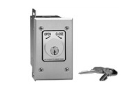
Can two key switches be wired to the same operator for access from both sides of the entrance?
Yes. Two key switches can usually control the same operator when both provide compatible dry-contact commands. For a basic momentary open command, their normally open contacts are typically wired in parallel to the same operator input and common. Separate open, close, stop, maintained, powered, or digital-control functions require different wiring and must follow the exact operator manual.
How Two Momentary Open Switches Normally Share One Input
When both stations are intended to perform the same function, each switch acts as another way to close the same control circuit. One conductor from each normally open contact connects to the documented OPEN, EXIT, CYCLE, SINGLE BUTTON, or ACCESS CONTROL input. The other conductor from each switch connects to the matching COM or COMMON terminal.
Because the contacts are arranged in parallel, turning either key completes the command circuit. The second switch remains inactive and does not need to be operated at the same time. This arrangement is appropriate only when both switches are isolated dry contacts and the selected board input is designed to accept that command.
The input function matters. An OPEN or EXIT terminal may open the gate and depend on the timer-to-close for closing. A CYCLE or single-button input may advance through open, stop, and close commands. Two switches sharing the same input will both produce the behavior assigned to that terminal.
Use Separate Contacts for Open and Close Commands
If both sides need independent OPEN and CLOSE control, each key station normally requires separate contacts and enough conductors for the two commands. The open contacts from both stations can be connected to the documented OPEN circuit, and the close contacts can be connected to the documented CLOSE circuit, provided the operator manual supports multiple controls on those inputs.
A three-position OPEN-OFF-CLOSE selector commonly provides one contact for OPEN and another for CLOSE. Its center position usually releases both contacts; it is not automatically a STOP command. Commercial door or gate operators that require a dedicated stop circuit may need a separate stop button or a compatible open-close-stop station.
Normally Closed Stop Circuits Use Different Wiring Logic
Multiple normally open activation contacts are commonly arranged in parallel so either device can issue a command. Multiple normally closed STOP or interlock contacts are commonly arranged in series so opening any one device breaks the circuit and stops or inhibits operation.
Do not place normally closed stop contacts in parallel unless the operator diagram specifically shows that arrangement. A parallel path could allow one closed device to bypass another device that is trying to open the stop circuit. Stop logic varies by operator, and some boards use a jumper, programming selection, or manufacturer-specific control station.
Maintained Key Switches Require Extra Caution
Two maintained switches can share a supported hold-open input, but either switch may keep the circuit active. Returning one station to OFF will not release the operator if the other station remains in HOLD OPEN. This can create confusion when personnel at opposite sides cannot see the other selector position.
Use maintained operation only with a terminal documented for continuous activation. A maintained contact on a momentary CYCLE or SINGLE BUTTON input can appear as a stuck command, pause the timer, block later controls, or produce model-specific behavior.
If hold-open control is needed from both sides, consider status indication or a secured access controller that shows whether the hold-open mode is active. Confirm where the key can be removed and whether an active position can be left selected unattended.
Garage Door Openers May Need an Adapter
Residential garage door openers may use a proprietary digital wall-control circuit rather than a conventional dry-contact input. Two wires at the wall console do not prove that two mechanical key switches can be placed across them. Those conductors may carry power, polarity-sensitive signals, lighting commands, lock functions, and digital communication.
When the opener does not provide a separate dry-contact input, each key switch may need to operate an approved adapter, interface, or relay arrangement. Verify the opener model, installed logic-board number, wall-control generation, and approved connection method before adding either station.
Plan the Wiring for Two Locations
Running each switch back to a secure junction or directly to the operator can simplify testing and avoid an exposed splice at one station. A daisy-chained circuit may work electrically, but damage or corrosion at the first station can disable the second. Label each cable so the two field circuits can be isolated during troubleshooting.
Confirm wire gauge, complete round-trip distance, conductor count, insulation rating, and wet-location suitability. Keep low-voltage control wiring separated from line-voltage conductors as required by the operator instructions. Outdoor runs also need appropriate conduit, bushings, strain relief, sealed entries, weather-resistant junctions, and surge protection.
Technician’s Corner
Field Note: Simultaneous Opposite Commands Are Board-Specific
If one user turns OPEN while another turns CLOSE, the result depends on the operator’s input priority and programming. STOP may override both, OPEN may take priority, or the board may ignore conflicting commands. Do not assume that the nearest switch controls the gate.
Field Note: Watch the Input LEDs During Testing
Operate each switch separately and confirm that the same intended input LED changes state. If one station activates a different LED, remains active after release, or causes a fault, inspect its contact configuration, terminal assignment, relay, and cable.
Field Note: Two Exposed Stations Double the Bypass Points
A dry-contact switch wired directly to OPEN and COMMON can be imitated by shorting its field conductors. For higher-security entrances, keep the final gate-opening relay inside a locked operator or access-control enclosure and use the outdoor stations only as inputs to that secure controller.
Field Note: South Florida Exposure Can Affect One Side Only
One station may face irrigation, wind-driven rain, salt air, or stronger afternoon sun than the other. Moisture, corrosion, thermal expansion, and conduit condensation can make one contact intermittent while the second station continues to work normally.
Before You Wire Two Key Switches
- Record the operator model, control-board part number, revision, and programming.
- Confirm that both switches provide isolated dry contacts with the required N.O. or N.C. logic.
- Identify whether both stations need open only, cycle, open-close, stop, or hold-open control.
- Verify momentary or maintained action and key-removal positions.
- Check conductor count, wire gauge, distance, conduit route, and weather rating.
- Confirm whether a relay, adapter, secure controller, or separate power supply is required.
- Test each station individually and then test simultaneous commands.
- Keep monitored photo eyes, sensing edges, stop circuits, and other required safety devices functional.
Final Compatibility Rule
Two key switches can commonly share one operator when their compatible normally open momentary contacts are wired in parallel to the same documented input and common. More complex control requires matching every command circuit separately. Before selecting hardware, verify the operator model, board generation, terminal logic, voltage, frequency when applicable, connector type, switch action, wire distance, and safety requirements.
Related Technical Categories
- Key Switches and Key Stations
- Gate Operator Control Boards
- Access-Control Relays and Controllers
- Garage Door Dry-Contact Adapters
- Low-Voltage Control Wire
- Weatherproof Enclosures and Conduit Fittings
