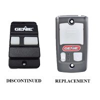
Why does the wall console light up but fail to open or close the gate or door?
A lighted wall console proves that some power is reaching the device, but it does not confirm that the movement command is reaching or being accepted by the operator. The cause may be incorrect console compatibility, reversed or damaged control wiring, a failed button contact, an open stop circuit, active safety logic, manual disconnect, or a control-board fault.
The Indicator Light and Movement Command May Use Different Circuits
An illuminated button, display, or backlight can receive accessory power even when the command circuit is open or connected to the wrong terminals. This is common with illuminated dry-contact stations, access-control interfaces, and commercial control stations that have separate power and switch connections.
Residential multifunction consoles can also power up while their door command is not communicating correctly. Some consoles use two conductors for both low-voltage power and encoded communication. The display or backlight may operate, but the logic board may not recognize the button command if the console generation, polarity, terminal assignment, or communication protocol is incorrect.
Confirm That the Console Matches the Installed Control Board
A replacement console should be matched to the operator model and the control board actually installed. An older operator may contain a later replacement board, conversion kit, or updated harness. In that case, accessory compatibility may follow the replacement board rather than the original operator production date.
A wrong-generation console can receive voltage yet fail to produce a command the board understands. Verify the console and board part numbers, production range, polarity, and any required adapter.
Check Whether the Board Registers the Button Command
Many gate and commercial operator boards include input indicators for OPEN, CLOSE, STOP, single-button, or other command terminals. Observe the appropriate indicator while pressing the wall control.
- The correct input indicator changes: the station and field wiring may be delivering the command, but the board is preventing movement because of another condition.
- No input indicator changes: inspect the button contact, cable continuity, common connection, terminal mapping, and console compatibility.
- The input stays active after release: look for a maintained relay setting, stuck button, wet cable, shorted conductors, or wiring on the wrong contact.
Do not create a test jumper unless the operator manual confirms that the terminal is a low-voltage dry-contact input. A digital wall-control bus, powered accessory terminal, or safety circuit must not be tested as though it were a basic push-button input.
An Open STOP Circuit Can Disable Every Command
Commercial door and gate stations often use separate open, close, stop, and common conductors. Depending on the operator family, the stop circuit may be normally closed and must remain complete during normal operation. A broken wire, loose terminal, incorrect replacement station, or failed stop contact can prevent both opening and closing even though the station light remains on.
Some gate operators use operator-specific three-button logic. A station with normally closed STOP contacts may not replace a station designed with all normally open contacts, and the reverse is also true. Match the exact station arrangement shown in the operator documentation.
Safety and Interlock Logic May Be Blocking Movement
If the board sees the wall command but does not run, check the operator's diagnostic indicators and safety inputs. Depending on the system and direction of travel, movement may be blocked by:
- a monitored photo eye or sensing edge fault;
- an emergency-stop or interlock circuit;
- an entrapment alarm that requires a documented reset;
- a commercial-door hoist or manual-chain interlock;
- an access-control inhibit or fire-system input;
- an unlearned limit, setup fault, or incorrect operating mode.
Safety faults commonly affect closing more than opening, but some operators inhibit all movement when a required monitored circuit, stop loop, or interlock is open. Do not bypass these inputs; identify the fault and verify the required device.
The Operator May Be Electrically Responding but Mechanically Disconnected
Listen and watch the operator when the button is pressed. A relay click, motor sound, warning device, or change in board indicators means the command may be reaching the system even though the gate or door does not move.
Check whether the manual release, trolley, carriage, clutch, hoist disconnect, or gate operator release mechanism is engaged according to the operator instructions. Also inspect for a jammed door, dragging gate, broken spring, seized hardware, activated motor overload, depleted battery under load, or failed motor drive component. A lighted console cannot confirm that the mechanical system is connected or free to move.
Residential Garage Console Clues
If a multifunction console can switch the opener light but the door button does nothing, part of the communication path is operating. The remaining problem may be a failed door button inside the console, an incompatible control feature, incomplete travel programming, an engaged manual release, or a fault inside the opener.
Technician's Corner
Powered Does Not Mean Compatible
Low-voltage accessories may illuminate across a broad voltage range, but their command electronics can still be incompatible. Two consoles that both light on the same pair of wires are not necessarily interchangeable.
Use Board Indicators to Divide the Problem
If the board's command indicator responds correctly, move the diagnosis away from the wall station and toward stop circuits, safety inputs, limit status, manual disconnects, motor protection, and board outputs. If the board never sees the command, remain focused on the station, cable, and terminal mapping.
South Florida Moisture Can Create Partial Operation
Humidity, salt-air exposure, wet conduit, insects, and corrosion can leave enough continuity to power an LED while adding too much resistance or leakage for a reliable command. Inspect exterior stations, junction boxes, cable entries, and low-voltage terminals for contamination.
A Separate Power Supply Can Hide an Operator Power Problem
An access-control panel or illuminated station may have its own power source. Its light can remain on even when the gate or door operator has lost AC power, has a disconnected battery, or has an open internal fuse. Verify power at the operator itself.
Before You Replace the Wall Console
- Verify the operator model, installed board number, and console part number.
- Confirm that the operator itself has AC or battery power.
- Check polarity, terminal labels, conductor continuity, and connector seating.
- Verify normally open or normally closed contact logic.
- Observe whether the correct board input activates when the button is pressed.
- Check stop, interlock, safety, limit, and alarm indicators.
- Confirm the manual release or trolley is engaged.
- Inspect the gate or door for binding, imbalance, or damaged hardware.
- Check outdoor boxes and cable entries for water, corrosion, or insects.
Related Technical Categories
- Wall Consoles and Control Panels
- Gate Operator Control Stations
- Commercial Door Control Stations
- Control Boards and Logic Boards
- Photo Eyes and Sensing Edges
- Low-Voltage Wiring Accessories
Parts-selection advisory: Verify the operator model number, control-board generation, console part number, voltage, wireless frequency when applicable, connector type, terminal function, polarity, NO/NC logic, and required safety-device configuration before selecting a replacement wall control.
Tagged Products