
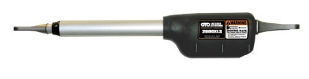
Can a bent gate hinge post or dragging gate make a new replacement arm appear weak?
Yes. A bent or moving hinge post, dragging gate, worn hinge, misaligned bracket, or binding lock can make a correctly sized replacement arm appear weak. These conditions increase mechanical resistance, alter actuator leverage, and raise motor current. Test the gate manually and verify bracket geometry, power under load, and operator diagnostics before condemning the new arm.
Why a Mechanical Gate Problem Can Look Like a Weak Actuator
A swing gate arm is designed to rotate a properly supported gate through a specific arc. It is not intended to lift a sagging leaf, straighten a twisted frame, hold a loose hinge post in alignment, or force the gate past a dragging point. When the gate structure adds resistance, the actuator must produce more force than the application should require.
The control board may interpret that higher motor current as an obstruction. Depending on the operator, the gate may slow, stop, reverse, display an overcurrent fault, or fail its travel-learning cycle. The new arm can therefore look underpowered even though the real problem is outside the actuator.
A Bent or Moving Hinge Post Changes the Operating Geometry
The hinge post establishes the gate’s pivot center. The actuator brackets are positioned in relation to that center, so a leaning, flexing, or partially detached post changes the geometry every time the gate moves. Even a small shift can reduce leverage near the open or closed position and force the arm to work at an inefficient angle.
Post movement can also twist the actuator sideways. The rear pivot and front clevis should articulate freely without bending the housing or loading the extension tube laterally. Side load increases friction inside the arm and can wear bushings, pins, seals, drive components, and bracket holes.
Look for cracked concrete, loose anchor bolts, split masonry, broken welds, rust at the post base, or a post that moves when the gate is pushed. Measure bracket positions from the true hinge center rather than from the outside edge of the post or column.
Dragging Gates Create Load That Static Weight Ratings Do Not Show
A gate may be within the operator’s published weight rating and still be difficult to move. Common causes include worn or dry hinges, a sagging frame, a wheel contacting the driveway, thermal expansion, a latch or electric lock that does not release, and a gate leaf that rubs a stop, curb, or adjacent structure.
Resistance is often not constant. The gate may move easily through the middle of its arc but tighten near fully open or fully closed. That pattern commonly causes the arm to stop or reverse at approximately the same position each cycle.
| Observed Symptom | Mechanical Condition to Check |
|---|---|
| Arm stalls as movement begins | Poor starting leverage, seized hinge, lock resistance, low voltage, or excessive gate load |
| Gate stops near one endpoint | Sag, ground contact, post movement, bad stop location, bracket geometry, or thermal binding |
| Actuator twists or chatters | Misaligned pivots, bent bracket, worn pin, loose post, or side-loaded clevis |
| Gate works in calm weather but reverses in gusts | Solid-panel wind load, flexible post, weak bracket attachment, or marginal operator sizing |
Disconnect the Arm and Test the Gate Through the Full Arc
Isolate power and use the model-specific manual release or disconnect procedure. Move the gate slowly from fully closed to fully open. It should remain supported and move smoothly in both directions without lifting, dropping, scraping, tightening, or pulling the post.
Do not judge the gate only at mid-travel. Check the first few inches of movement, the final approach to each stop, and the point where the electric lock or latch engages. Observe the hinge post and brackets while a second person moves the gate. Any visible post deflection or bracket movement requires correction before actuator diagnosis continues.
Check Voltage and Current Under Actual Gate Load
A mechanical problem and an electrical problem can produce similar symptoms. Measure supply and motor voltage under load using the test points specified for the exact operator. Weak batteries, corroded terminals, undersized field wiring, wet splices, or a damaged board output can reduce available torque when the gate is connected.
If full voltage reaches the arm but current rises sharply where the gate binds, the gate or mounting geometry is the stronger suspect. If voltage collapses at the board or actuator connector, inspect the power system, harness, terminals, and control-board output before replacing the arm.
Technician’s Corner
Do Not Increase Force to Compensate for Drag
Increasing force or current sensitivity may temporarily move the gate, but it can hide a structural or alignment problem and reduce obstruction sensitivity. Correct the gate and bracket condition first, then set force according to the operator procedure.
South Florida Conditions Can Move and Corrode Gate Structures
Salt air, irrigation, wind-driven rain, and corrosion can weaken a post base, hinge weld, bracket plate, or pivot pin. Heat can also expand long metal gates enough to create endpoint drag that is absent during cooler testing.
Wind Load Can Deflect the Post While the Gate Is Moving
A solid wood, composite, or sheet-metal leaf acts like a sail. The gate may move freely by hand in calm conditions but load the actuator and flex the post during gusts. Evaluate panel area and site exposure, not just static gate weight.
A New Arm May Reveal an Existing Problem
A replacement arm may use different seals, gearing, current feedback, or freshly learned force values. That does not mean the new arm is weaker. It may simply expose resistance that the worn previous system had been forcing through.
Before You Blame the Replacement Arm
- Verify the replacement arm, operator, and control-board part numbers.
- Move the disconnected gate through its complete arc in both directions.
- Inspect hinges, post base, welds, anchors, brackets, pins, and bushings.
- Check for gate sag, driveway contact, stop interference, and lock resistance.
- Compare hinge-center and bracket dimensions with the correct installation drawing.
- Measure board and actuator voltage while the gate is moving.
- Record overcurrent, obstruction, limit, and position-sensor diagnostics.
- Confirm gate length, weight, construction, duty cycle, and wind exposure.
Retest the Complete System After Mechanical Correction
After repairing the post, hinges, gate alignment, or brackets, verify motor direction and repeat the required limit or travel-learning procedure. Recheck slowdown, force or current sensing, physical stops, automatic-close timing, dual-leaf delay, and electric-lock operation.
Test the manual release and all required monitored photo eyes, edge sensors, and stop inputs before normal operation. Before selecting another replacement part, verify the model number, part number, voltage, frequency where applicable, connector type, limit or encoder system, control-board generation, mounting geometry, and gate application.
Related Technical Categories
Tagged Products


