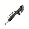
How do I identify the correct replacement arm for my swing gate operator?
The correct replacement arm must match the swing gate operator’s manufacturer, exact model and generation, operating voltage, control-board connector and feedback system, mounting geometry, travel, and single- or dual-gate role. Do not identify it by appearance alone. Record every label and part number, then compare the existing arm, brackets, harness, limits, and manual before selecting a replacement.
Start With the Operator Family, Not the Arm’s Appearance
“Swing gate arm” can describe several different assemblies. A linear actuator extends and retracts between a post bracket and gate bracket. A pad-mounted operator uses an external linkage arm connected to a gearbox output shaft. An articulated operator uses jointed arms for columns or wide posts. Underground and hydraulic systems use different drive assemblies again. These designs are not interchangeable even when they move a gate through the same angle.
First identify the complete operator system. Look for labels on the control cabinet, motor housing, actuator body, gearbox cover, or inside the operator enclosure. Record the manufacturer, full model number, serial number, manufacture date, and every visible assembly or service part number. A control box model alone may not identify the actuator because some manufacturers pair one board family with multiple arm models.
Record the Details That Determine Compatibility
| Identification Point | Why It Matters |
|---|---|
| Operator and arm part numbers | Separates look-alike actuator families and superseded generations. |
| Motor voltage and type | The replacement must match AC or DC operation and the board’s motor output. |
| Control-board model and revision | Determines connector style, limit inputs, encoder logic, current sensing, and programming. |
| Single, primary, or secondary arm | Dual-gate versions may use different harness lengths, terminals, delay logic, or communication hardware. |
| Mounting and travel dimensions | Stroke, retracted length, pivot spacing, brackets, and opening angle control mechanical fitment. |
Match the Electrical and Feedback System
Voltage is only the first electrical check. Compare the number of motor wires, connector shape, pin count, cable length, wire colors, grounding method, and any separate limit or encoder conductors. One arm may use mechanical limit switches, while another may use magnetic limits, Hall sensors, an encoder, or control-board current sensing. A motor can physically run while the board still cannot recognize position or stop points.
Do not splice a new connector onto an old harness unless the manufacturer’s wiring information confirms every conductor and function. Similar plugs can carry different pin assignments. Reversed motor polarity may change direction on some DC systems, but limit and encoder wiring cannot be treated as interchangeable motor leads. Also verify whether a newer replacement requires a matching board, adapter harness, firmware revision, or complete conversion kit.
Confirm Mechanical Fitment and Gate Geometry
Measure the existing arm before removing brackets. Record the pin-to-pin length when retracted, usable stroke, tube or body dimensions, rear pivot style, front clevis size, bolt diameter, and post-to-hinge geometry. Photograph the post bracket, gate bracket, cable exit, manual release, and limit-adjustment area. For pad-mounted operators, record the output-shaft diameter, keyway, crank arm, connecting arm, and handed installation.
Bracket geometry controls leverage, travel, speed, and the force transferred into the gate. An actuator with the correct voltage but the wrong stroke or pivot dimensions may bottom out internally, fail to reach the limit, bind near the hinge, or place excessive load on the drive screw and brackets. Push-to-open and pull-to-open installations can also require different bracket positions or control settings.
Do Not Use the New Arm to Compensate for a Bad Gate
Disconnect the operator and move the gate through its full travel by hand. The leaf should remain supported, swing smoothly, and avoid dragging, sagging, twisting, or tightening near the open and closed positions. Check hinges, stops, welds, posts, locks, and bracket alignment. A replacement arm can fail quickly when it is forced to overcome gate drag or a shifting hinge post.
Gate weight is not the only load factor. Leaf length, solid infill, wind exposure, opening angle, hinge offset, slope, and cycle demand all change the torque required. A visually similar residential actuator should not replace a heavier-duty arm simply because the mounting holes appear close.
Technician’s Corner
Salt Air and Moisture Can Damage More Than the Motor
In South Florida, inspect the cable gland, connector pins, limit-switch compartment, mounting hardware, and lower housing for corrosion or water tracks. Green copper, swollen seals, or rust near the cable entry may point to harness or feedback damage rather than a failed motor alone.
Wind Load Can Make a Correct Arm Look Undersized
Solid wood, composite, and sheet-metal swing gates act like sails. A system that works in calm weather may overload, reverse, or stall during gusts. Match the arm to gate length, construction, site exposure, and operator rating, not just the measured gate weight.
Battery Voltage Without Load Can Be Misleading
A battery-backed operator may show normal resting voltage but collapse when the arm starts. Before condemning the actuator, check voltage at the board and motor output during movement. Weak batteries, corroded terminals, undersized wiring, or a failing charger can imitate a seized or weak arm.
Surge Damage Can Affect Only One Board Circuit
After lightning or a utility surge, a control board may still power accessories while its motor output, limit input, or encoder circuit is damaged. Confirm board output and feedback operation before installing another actuator into a system that may have caused the original failure.
Before You Choose a Replacement Part
- Verify the complete operator model, serial range, and manufacture date.
- Match the actuator or linkage assembly part number and any documented supersession.
- Confirm AC or DC voltage, connector, pinout, harness length, and grounding.
- Identify mechanical limits, magnetic limits, encoder, Hall sensor, or current-sensing logic.
- Confirm single-gate, primary, secondary, left-hand, or right-hand requirements.
- Compare stroke, closed length, pivot points, brackets, bolt sizes, and opening geometry.
- Check whether the replacement includes brackets, hardware, cable, release parts, or only the arm assembly.
- Verify the gate moves freely and remains within the operator’s application limits.
Recommission the Complete Gate System
After an arm replacement, limits, direction, force or current sensing, slowdown points, dual-gate delay, and electric-lock timing may need to be set again. Recheck all monitored photo eyes, edge sensors, stop inputs, manual release functions, and entrapment zones. A correctly matched arm is only one part of a safe operating system.
Related Technical Categories
- Swing Gate Openers
- Replacement Arms
- Gate Opener Circuit Boards
- Gate Hardware
- Photo Eyes and Safety Devices
Before selecting replacement hardware, verify the operator model number, arm part number, voltage, frequency where applicable, connector type, board revision, feedback method, mounting geometry, and operator generation. When any identification point is uncertain, match the existing assembly against the correct parts diagram and operator manual rather than relying on appearance.
Tagged Products