
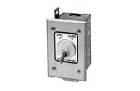
What wire type and gauge should be used between the key switch and the operator?
For most basic dry-contact key switches, use two-conductor copper low-voltage control cable sized according to the operator manual. Eighteen AWG is a common gate and commercial-control choice; shorter residential runs may permit smaller conductors. Outdoor or underground wiring must be wet-location rated, separated from line voltage, and increased in gauge when distance or powered accessories create voltage drop.
Start With the Operator Manual, Not a Universal Wire Size
There is no single wire gauge that applies to every gate operator, garage door opener, key station, and cable distance. The correct conductor size depends on the board input, total round-trip length, terminal size, cable environment, and whether the circuit carries only a dry-contact signal or also supplies power to a lamp, heater, relay, or electronic accessory.
Manufacturer instructions take priority. Some gate and commercial-door control stations specify 18 AWG control wire. Certain commercial operators publish very long allowable low-voltage runs, but those limits belong only to that operator family and wiring method. Do not transfer a published distance from one board to another.
Wire for a Basic Two-Wire Dry-Contact Key Switch
A simple momentary normally open key switch usually needs two conductors: one for the operator command input and one for the matching COMMON terminal. Because the switch only closes the board’s sensing circuit, current is normally low. Conductor selection is still important because long runs, small wire, corroded splices, and wet terminals add resistance and can prevent the board from recognizing a clean closure.
For outdoor gate work and many commercial control stations, 18 AWG stranded copper is a practical starting point when the manufacturer does not specify something different. Some short indoor residential garage-control circuits may permit 20 or 22 AWG cable, but smaller conductors should not be assumed acceptable for a long pedestal run or underground gate installation.
When 16 AWG or a Larger Conductor May Be Needed
A larger conductor may be appropriate when the run is long, the manual requires it, or the key station includes powered components. A mechanical dry contact and an illuminated or heated key station are different loads. LEDs, lamps, buzzers, relay coils, heaters, and access-control electronics can experience voltage drop even when the switch contact itself still works.
Calculate powered circuits using the full round-trip distance, supply voltage, current draw, and minimum operating voltage at the station. Do not increase wire size blindly if the operator terminal cannot accept the conductor. A listed terminal block or properly rated transition may be needed near the board.
Use the Correct Cable for the Environment
Indoor, Dry Locations
For an indoor dry-contact run, use copper low-voltage control cable that meets the operator instructions and local requirements. A simple station normally uses two conductors, while an OPEN-OFF-CLOSE switch may need three or more. A true OPEN-CLOSE-STOP station, tamper switch, indicator, heater, or separate relay can require additional conductors.
Outdoor and Underground Locations
Outdoor posts, masonry columns, pedestals, and underground conduit require cable or individual conductors listed for wet locations. Conduit does not guarantee a dry interior; condensation and water commonly collect in underground raceways. Direct-burial cable should be used only where the cable is specifically listed and the installation method permits direct burial.
Use weatherproof boxes, listed conduit fittings, bushings, strain relief, sealed entries, and corrosion-resistant terminals. Avoid unprotected splices underground. Where a splice is unavoidable, place it in an accessible enclosure and use a connection method rated for the environment.
Keep Low-Voltage Control Wiring Separate From Line Voltage
Do not route ordinary low-voltage key-switch cable in the same conduit as motor or incoming power conductors unless the operator instructions, conductor insulation ratings, and applicable electrical requirements specifically permit that arrangement. Separate routing reduces insulation concerns and limits electrical noise induced by motors, contactors, transformers, and power wiring.
Use conduit sweeps rather than tight elbows so the cable can be pulled without damaging insulation. Protect cable passing through metal posts with bushings or glands, and leave enough service loop to remove the key-switch faceplate without pulling on the terminals.
Should the Cable Be Shielded or Twisted?
A basic mechanical dry-contact key switch often does not require shielded cable. Twisted-pair or shielded cable may be useful when the manufacturer specifies it, the run is long, or the cable passes near known noise sources. Shield termination must follow the equipment instructions; grounding a shield incorrectly can create another current path or noise problem.
Do not substitute network cable merely because it contains multiple conductors. Its conductor size, outdoor rating, mechanical strength, connector method, and permitted use must match the installation. Copper-clad aluminum cable should not be treated as equivalent to copper control wire.
Technician’s Corner
Technical Field Note: Round-Trip Length Matters
A key switch located 150 feet from the operator creates approximately 300 feet of conductor path in a two-wire circuit. Evaluate resistance and voltage drop using the complete outgoing and return length, not only the one-way distance.
Technical Field Note: Moisture Can Make Good Wire Test Bad
In South Florida, water entering a pedestal or conduit can corrode copper, terminals, and splices. A cable may pass a basic continuity test but develop unstable resistance during rain, heat, or vibration. Inspect insulation resistance and connections when operation changes with weather.
Technical Field Note: Long Outdoor Runs Need Surge Planning
A long field cable can carry lightning-induced energy toward the control board. Use the grounding, bonding, and low-voltage surge-protection method approved for the operator and site. Surge protection does not correct undersized wire or poor splices.
Technical Field Note: Count Functions Before Pulling Cable
Two conductors are enough only for one isolated contact. Separate OPEN and CLOSE commands, a normally closed STOP loop, illumination, a heater, tamper monitoring, or a remote relay require additional conductors. Pulling spare conductors can simplify future changes when the cable and conduit design permit it.
Before You Choose the Wire
- Record the operator model, control-board part number, revision, and terminal function.
- Confirm whether the circuit is dry contact, powered, supervised, or digitally communicating.
- Verify the manufacturer’s conductor gauge, maximum distance, and cable-type requirements.
- Calculate the complete round-trip length and any powered accessory load.
- Count conductors for OPEN, CLOSE, STOP, tamper, indicator, heater, and relay functions.
- Select copper cable rated for indoor, outdoor, wet-location, conduit, or direct-burial use as applicable.
- Plan separation from line voltage, protected entries, accessible splices, and surge protection.
- Confirm that terminal blocks, ferrules, connectors, and enclosure seals fit the selected conductor.
Final Wire-Selection Rule
For a basic outdoor gate key switch, 18 AWG two-conductor stranded copper control cable is a common starting point, not a universal specification. Use the exact gauge and cable type approved for the operator, run length, and environment. Verify model number, board generation, contact logic, voltage, connector type, conductor count, wet-location rating, and powered accessory load before selecting the wire.
Related Technical Categories
- Key Switches and Key Stations
- Low-Voltage Control Wire
- Weatherproof Junction Boxes and Conduit Fittings
- Access-Control Relays and Interfaces
- Gate and Garage Operator Control Boards
- Low-Voltage Surge Protection
