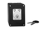
How far can a key switch be installed from the gate or garage door operator?
There is no universal maximum distance. A key switch can often be installed farther away when it provides only an unpowered dry-contact command, but the allowable run depends on the operator manual, wire gauge, circuit resistance, electrical noise, surge exposure, and whether the switch also powers a light, heater, relay, or access-control device.
The Maximum Distance Is Set by the Control Circuit
A basic mechanical key switch usually operates as a remote contact closure. Turning the key connects an activation input to the operator’s common terminal. Because the switch is not powering the gate motor or garage door motor, the control circuit may support a much longer cable run than the operator’s incoming power wiring.
That does not make the distance unlimited. Every conductor adds resistance, capacitance, and exposure to induced voltage. Corroded splices, undersized cable, wet underground boxes, shared conduit, and lightning-related surges can make a long run unreliable even when the key switch works correctly on a short test lead.
Start With the Operator Manual
Use the wiring section for the exact operator and control-board generation. Look for a maximum low-voltage control-wire distance, conductor-size table, required cable type, or instructions for long-distance controls. Some commercial door operators publish control-wire limits as long as 1,000 feet, but that figure applies only to the specific operator and wiring method identified by the manufacturer. It should not be transferred to an unrelated gate board or residential garage opener.
If the manual gives no maximum distance, do not assume that any length is acceptable. Confirm the input type and use the board manufacturer’s wiring guidance. The safest design is the shortest practical run with correctly sized copper conductors and protected routing.
Dry-Contact Runs Behave Differently From Powered Runs
Unpowered Momentary Key Switch
For a simple normally open dry-contact input, the cable carries only the operator’s sensing circuit. Voltage drop may be relatively small, but total loop resistance still matters. The loop includes the outgoing conductor, return conductor, switch contacts, splices, and terminal connections. A board may fail to recognize the command when that total resistance becomes excessive.
Illuminated, Heated, or Electronic Key Stations
If the station contains an LED, lamp, heater, buzzer, timer, relay, card reader, or other powered component, distance must also be calculated as a power circuit. Verify the accessory voltage, AC or DC type, current draw, polarity, minimum operating voltage, and available operator accessory capacity. A wire size that reliably carries a dry-contact command may be too small to power an illuminated or heated station over the same distance.
Garage Door Wall-Control Circuits
Residential garage door openers require special caution. A two-wire wall-control circuit may carry digital communication, accessory power, lock commands, or polarity-sensitive signals. Extending that circuit is not the same as extending a conventional dry-contact input. Use the operator’s specified wall-control wire and distance guidance, or use an approved dry-contact interface located where the manufacturer permits.
Wire Gauge, Cable Type, and Routing Matter
Longer distances generally require larger conductors to reduce resistance, but wire gauge should be selected from the operator or accessory documentation rather than from a generic chart alone. Count the full electrical path, not just the one-way distance from the key switch to the operator.
Use cable with an insulation rating suitable for the installation. Underground conduit, direct-burial sections, wet locations, exposed pedestals, and indoor garage walls can require different cable and enclosure methods. Low-voltage control wiring should not share a conduit with line-voltage motor or power conductors unless the complete installation and insulation system are specifically permitted by the applicable instructions and electrical code.
Twisted-pair or shielded cable may be useful when the manufacturer calls for it or when the run passes near motors, contactors, fluorescent lighting, variable-frequency equipment, or other sources of electrical noise. Shielding must be terminated according to the control manufacturer’s instructions; grounding both ends without guidance can create additional problems.
When to Use a Relay Near the Operator
For a very long run, a powered access-control station, or a cable route exposed to electrical noise, the better design may be to place an isolated relay near the operator. The remote key switch or access system controls the relay, and the relay provides a short dry-contact closure directly at the operator input.
This does not eliminate the need to engineer the remote circuit correctly. The relay coil, power supply, enclosure, surge protection, and fail-safe or fail-secure behavior must still match the application. The operator-side relay contacts must also be suitable for the required normally open, normally closed, momentary, or maintained command.
Technician’s Corner
Field Note: Measure Round-Trip Resistance
A long cable can look intact and still have enough resistance from small conductors, corroded splices, or water-damaged terminals to prevent reliable activation. Testing resistance with power removed is more useful than judging the cable by appearance.
Field Note: Storm Exposure Changes the Design
In South Florida, long outdoor control runs can act as a path for lightning-induced energy. Surge protection, proper grounding, separation from power conductors, sealed junctions, and corrosion-resistant terminals become more important as the distance and outdoor exposure increase.
Field Note: Intermittent Operation May Be Cable Related
If the key switch works at the operator but fails at the pedestal, the problem may be voltage drop, resistance, induced noise, a damaged underground conductor, or a wet splice rather than an incompatible switch. Test the switch and cable separately before replacing the control board.
Field Note: A Maintained Contact Can Complicate Testing
A maintained key switch can leave the input continuously active. Confirm that the operator is designed for that command before using a long run or relay interface. Many cycle inputs expect a brief momentary closure instead.
Before You Plan the Wire Run
- Record the operator model, control-board number, and production generation.
- Identify whether the input is dry contact, powered, supervised, or digitally communicating.
- Confirm momentary or maintained operation and N.O., N.C., or SPDT contacts.
- Check the manufacturer’s maximum distance, wire gauge, and cable-type requirements.
- Calculate the complete round-trip circuit length and any powered accessory load.
- Count required conductors for open, close, stop, indicator, heater, or relay functions.
- Review conduit separation, wet-location rating, shielding, grounding, and surge protection.
- Consider an isolated relay near the operator when the approved direct run is impractical.
Final Distance Rule
The correct answer is the maximum distance allowed by the exact operator, control board, switch circuit, cable, and installation environment. Verify the model number, board revision, voltage, current draw, contact type, connector or terminal arrangement, conductor gauge, cable rating, and operator generation before selecting or extending key-switch hardware.
Related Technical Categories
- Key Switches and Key Stations
- Gate Access Control Devices
- Garage Door Wall Controls
- Access Control Relays and Interfaces
- Low-Voltage Control Wire
- Surge Protection and Weatherproof Enclosures
Tagged Products