
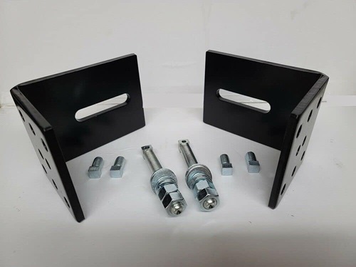
Can I reuse my existing gate brackets when installing a new replacement arm?
You can reuse existing gate brackets only when they are the correct manufacturer-approved brackets for the replacement arm, remain structurally sound, and preserve the required hinge-to-pivot geometry. Replace or reposition them if the new arm uses different stroke, pivot dimensions, push-to-open geometry, pin sizes, or mounting instructions, or if the brackets are bent, cracked, corroded, or modified.
Bracket Fit Is More Than Whether the Pin Goes Through
A replacement actuator may physically connect to an existing post bracket and gate bracket while still being mounted incorrectly. The bracket positions determine the actuator angle, mechanical leverage, usable stroke, opening speed, and the force transferred into the gate leaf. A small change in pivot location can make the arm bind near one endpoint, bottom out internally, or fail to reach the open or closed position.
Start by identifying the complete operator model, replacement-arm part number, and the installation drawing for that exact arm. Compare the specified measurements from the gate-hinge center to the actuator pivot and gate attachment point. Do not assume that brackets from an older model, a different stroke length, or a visually similar actuator use the same geometry.
When Existing Brackets May Be Reused
Reusing the existing brackets is normally reasonable when the replacement is the same actuator assembly or a manufacturer-documented direct supersession, and the original mounting dimensions remain correct. The rear pivot style, front clevis width, pin diameters, bracket offsets, actuator stroke, and retracted length must all match.
The brackets should also remain level, rigid, and correctly aligned with the actuator. The arm should articulate without twisting the housing or placing side load on the extension tube. Push-to-open and pull-to-open installations must be checked separately because the required pivot location, motor direction, and limit assignments may differ.
| Reuse Check | What Must Be Confirmed |
|---|---|
| Bracket geometry | Hinge-center measurements, pivot position, gate attachment point, opening angle, and actuator alignment. |
| Mechanical fit | Clevis width, pin diameter, bracket thickness, spacers, bushings, and retaining hardware. |
| Structural condition | No cracks, bending, elongated holes, loose welds, severe corrosion, or movement under load. |
| Replacement-arm specifications | Correct stroke, retracted length, pivot design, voltage, limit system, and operator generation. |
When the Old Brackets Should Be Replaced or Repositioned
Replace the brackets when the new arm is supplied with model-specific hardware or the replacement instructions show different mounting dimensions. A documented conversion may require a new pivot arm, gate bracket, spacers, or mounting plate even when the new actuator resembles the old one.
Old brackets should not be reused when pin holes are elongated, bushings are loose, plates are bent, welds are cracked, or corrosion has reduced the metal thickness. Also inspect fabricated brackets and previous field modifications. A shortened, flipped, or offset bracket may have been used to compensate for a sagging gate, incorrect hinge location, or mismatched actuator.
Check the Gate Before Blaming the Brackets
Disconnect the operator and move the gate through its full travel by hand. The leaf should remain supported and swing freely without dragging, tightening near the endpoints, or shifting the post. Worn hinges, thermal expansion, damaged stops, or a binding electric lock can overload the bracket connection and make correct geometry appear wrong.
Confirm that the gate reaches its physical open and closed stops without relying on the actuator as the structural stop unless the manufacturer specifically designs the system that way. The arm should not be forced to hold a sagging gate square or pull against a rigid stop after the limit has been reached.
Technician’s Corner
Field Note: Measure From the Hinge Center
Bracket measurements should be referenced from the actual gate-hinge pivot, not from the edge of a post, column, or decorative cover. A masonry column can hide the hinge center and create a misleading measurement. Record the true pivot before relocating a bracket.
Field Note: South Florida Corrosion Often Starts Behind the Plate
Salt air, irrigation, and trapped moisture can corrode the hidden side of a welded bracket. Surface paint may look acceptable while rust is developing between the plate and post. Inspect the weld perimeter, lower edge, pin holes, and any area where water can collect.
Field Note: Do Not Weld With Operator Electronics Energized
Before welding or grinding near the gate, isolate the operator according to the manufacturer’s procedure, including disconnecting applicable power and batteries. Welding current and electrical transients can damage a control board, charger, receiver, or actuator feedback circuit.
Field Note: Wind Load Magnifies Weak Bracket Geometry
A solid-panel gate can apply large reversing loads to the brackets during gusts. A bracket that appears stable during calm testing may flex or tear under wind load. Verify the operator application, gate construction, weld area, and support structure.
Before You Reuse Existing Gate Brackets
- Verify the old and new actuator part numbers and documented supersession.
- Compare the exact hinge-to-pivot and hinge-to-gate-bracket measurements.
- Match stroke, retracted length, pivot style, clevis, pins, spacers, and bushings.
- Confirm push-to-open or pull-to-open geometry and required opening angle.
- Inspect plates, welds, holes, fasteners, corrosion, and movement under load.
- Check that the gate swings freely and the hinge post remains stable.
- Determine whether the replacement package includes new model-specific brackets.
- Verify clearance through the complete opening and closing arc before final attachment.
Set Up and Test the Operator After Mounting
After the bracket location is confirmed and permanently secured, verify motor direction and reset the limits or travel-learning procedure as required. Check slowdown, force or current sensing, physical stops, dual-leaf delay, and electric-lock timing. Test the manual release and all required monitored photo eyes, edge sensors, and stop inputs before normal operation.
Related Technical Categories
Before selecting or mounting replacement hardware, verify the operator model, arm part number, voltage, frequency where applicable, stroke, connector type, limit system, operator generation, pin sizes, bracket dimensions, and hinge geometry. Reuse existing brackets only when the replacement documentation and a physical inspection confirm that they remain correct for the new arm.
Tagged Products


